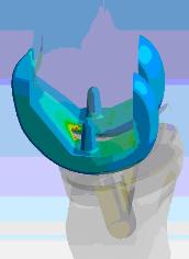
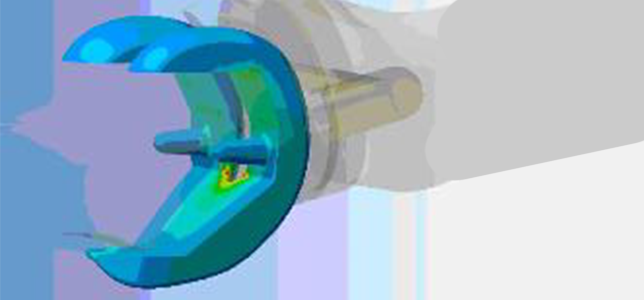
 Finite Element Analysis (FEA), or computer simulation, is a powerful tool in the medical product development industry, but it is often misunderstood or misused. If you decide not to read much further, understand this one thing: FEA is a prototype reducing tool, not eliminating. Any one of the myriad of simulation programs can output very colorful and technical looking plots, but detailed experience and physical testing are critical to back them up. The only way to know for certain if you are right is to test it.
 Simulation tools from SolidWorks, Pro/E, and even ANSYS have become both easier to use and more powerful. The development road to simulation is a pretty easy path to follow.
Hand Calculations
The most critical starting point is hand calculation. Whether it’s a free body diagram, energy conservation equations, or drop test G load estimations, everyone should work it out on paper first to get a feel for the order of magnitude inputs/outputs you are dealing with. Paper is cheap and good analysts need to develop their gut when scrutinizing results farther down the road.
Physical Testing
Nothing beats the real world when it comes to experience. You need to understand how hanging weights, heating up an enclosure with and without a fan, or the true shock inputs from a four-foot drop affects part design. There is a physical reason why you want larger rounds on bolt bosses. With strain gages and hanging weights, it takes minutes to actually see why. With the advent and popularity of desktop 3D printers, you can be up and testing white-sheet-of-paper concepts in hours. Remember that stress is a function of Force/Area, so the material will not affect the high-stress location, just the ultimate load.
Basic Linear Simulation
When looking to enter the computer world, there are many programs to choose from. I am not going to go into the depths of linear and non-linear analysis and what that means. If you want to analyze parts and keep them below the yield strength of the desired material, you are in the linear world. Most people tend to stick with programs that neatly integrate with their CAD package, so SolidWorks Simulation and Pro/E’s Mechanica are great places to start. Comparative studies at this level are your best friend for design optimization. If you have a tested and proven part, run it through simulation and iterate your design. Based on the results of the known good part, you will quickly see the percentage increase or decrease in strength as you change the design.
Complex Non-Linear Simulation
After you master the basics of simulation, prove your designs with testing, and know right away if a simulation result looks wrong, it’s time to step up to a more dynamic and flexible simulation program. The non-linear world examines complicated contact, fluid/gas flow, and materials (think rubber or compressible fluids). When given the opportunity (and budget), I always go for analyzing assemblies as opposed to individual parts. All too often when looking at individual parts, the assumed assembly constraints are compromised estimations. You can learn a ton from part-to-part interactions that may not react as you expected. In terms of computational fluid dynamics (CFD), we are continually shrinking packaging and power requirements. A great way to see if you need a fan is to analyze it; but to do that, you need the internal assembly to accurately model the air flow path. In terms of software, I can’t say enough about ANSYS. No other FEA package I have worked with has the solution monitoring functionality that ANSYS has. You have multiple tools and data monitoring features to predict if an analysis run is going to fail before it finishes, which can save hours from big runs.
Each of the steps above has its time and place whether you are just starting out or are a seasoned veteran. In the product development world, billable time is literally money. You always have time to do a quick hand calc., but you may not have time to fully analyze a ten-part assembly. Experience will dictate where you can simplify and expedite the process for usable data, or when you have to put your foot down and argue for analyzing the whole assembly. In closing, here are a couple tips I learned the hard way:
- Trust your gut. If it looks wrong, it probably is.
- Mesh density in high-stress areas for h-method solvers (vast majority except Pro/Mechanica, p-method) is absolutely critical to accurate answers.
- When physical testing, do not verify your analysis results on deflections only, unless that is the specific data you are after. FEA programs solve directly for displacements, but stresses are estimated based on equations directly related to element accuracy.
- Check your work with other people. Farm has a dedicated Stress Group to review even the simplest analysis run. It’s very easy to get lost in the minutia and lose the big picture.
- There is no such thing as a quick analysis. Take your time and do it right, including some kind of verification.
If you have any questions please feel free to contact me or leave a comment.
